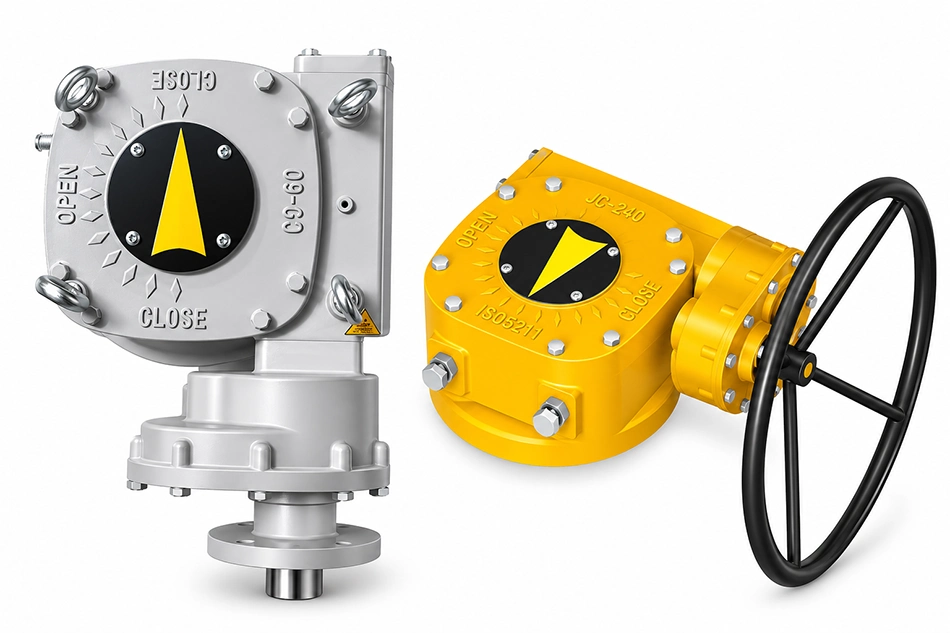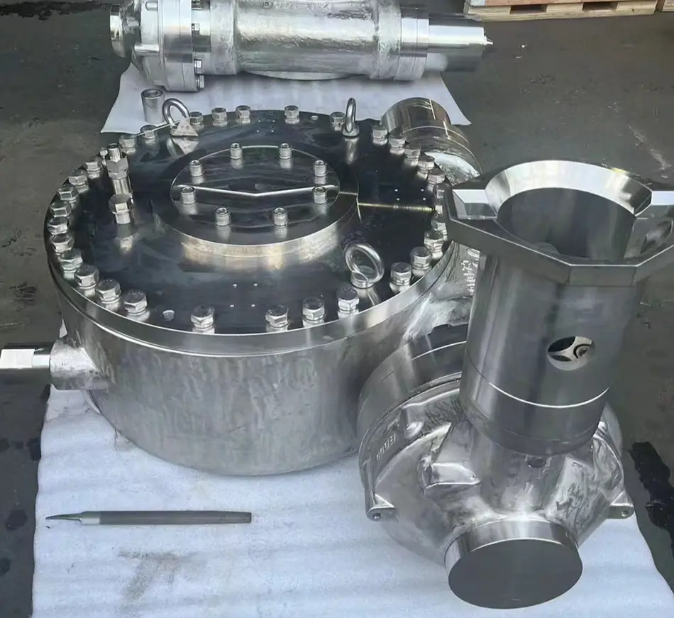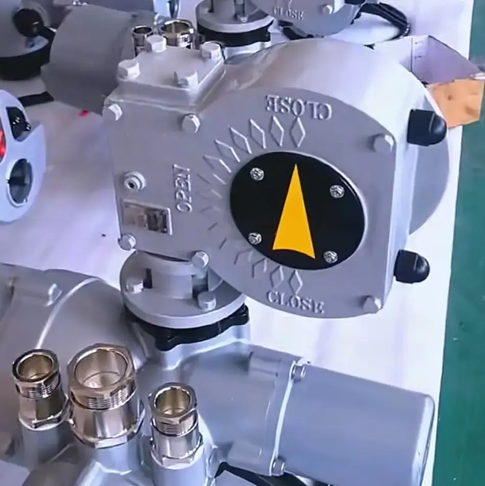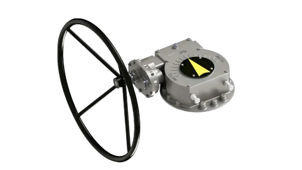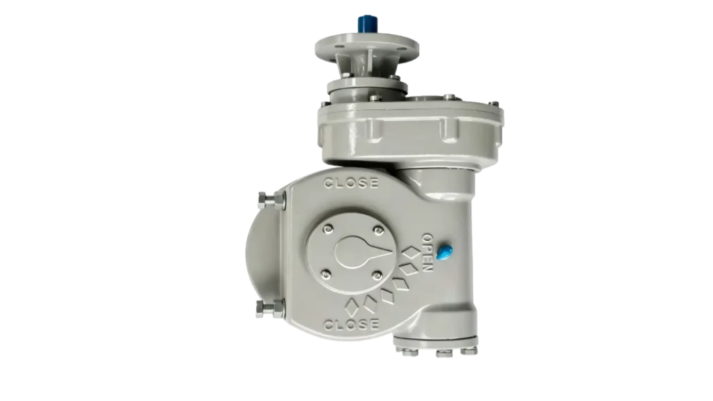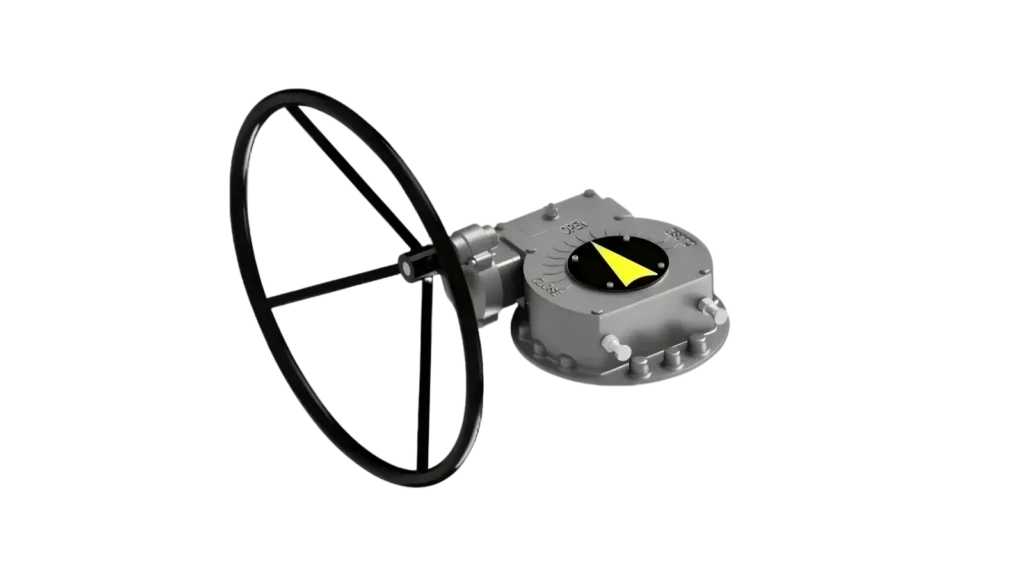
Torque matching for a high-performance butterfly valve is nothing like sizing a gearbox for a standard ball valve. Buyers who treat them the same often discover the difference the hard way — through field failures, valve chatter, and premature gearbox damage. Getting this pairing right requires a fundamentally different evaluation framework.
A high-performance butterfly valve (HPBV) generates dynamic, non-linear torque demands that standard gearbox selection methods are not designed to handle. The eccentric disc geometry creates torque spikes at unseating, fluid dynamic forces continuously push against the disc during flow, and triple-offset designs rely on torque — not position — to achieve a seal. Matching the wrong gearbox to an HPBV introduces mechanical risk at every stage of valve operation.
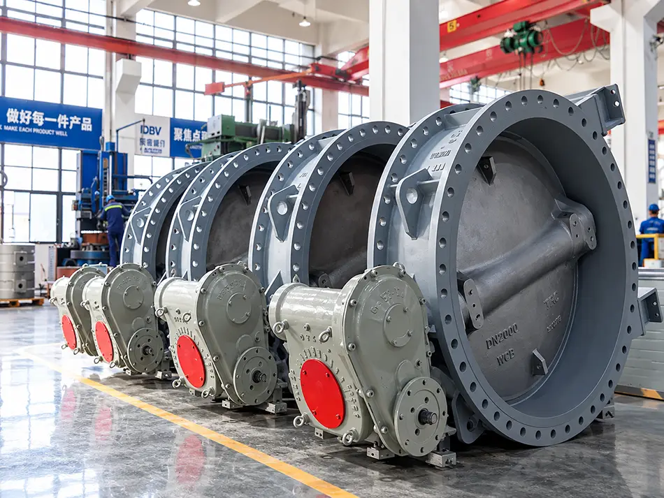
Understanding why HPBV torque behaviour differs from a ball valve or a resilient-seated butterfly valve is the foundation of every reliable gearbox selection. The five engineering challenges below are where most mismatches originate — and where the most expensive failures occur.
Why Does Fluid Dynamic Torque Matter More in Butterfly Valves Than Ball Valves?
Most buyers understand that a ball valve's dominant torque demand comes from seat friction — the sealing interface creates resistance, and the gearbox overcomes it. A high-performance butterfly valve behaves differently. In large-diameter or high-velocity applications, the fluid itself generates a powerful moment acting directly on the disc1.
When fluid flows past a partially open butterfly disc, it creates a hydrodynamic torque that continuously tries to force the disc either fully open or fully closed. At high flow velocities, this force is not negligible — it becomes a significant component of the total torque demand and must be accounted for in gearbox selection.
The Self-Locking Requirement
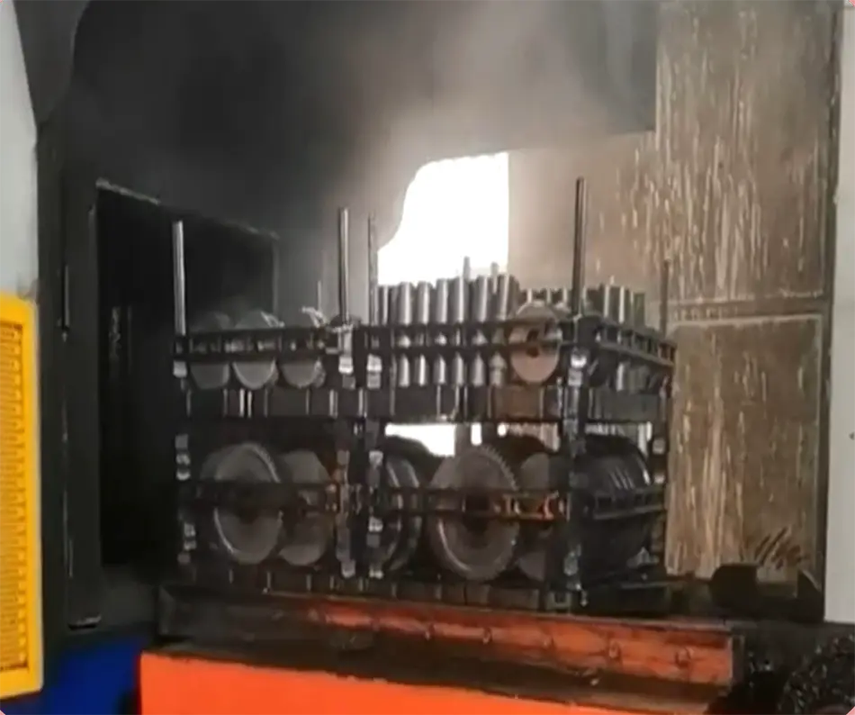
This is where the self-locking ratio of the worm gearbox becomes critical. A worm gearbox is self-locking when the worm lead angle is low enough that the output shaft cannot back-drive the input. In a ball valve application, self-locking is a convenience. In a high-performance butterfly valve application — especially at large diameters — it is a structural protection requirement.
If the worm gear ratio is insufficient to provide reliable self-locking:
- The disc can flutter or chatter in the half-open position under dynamic flow conditions
- Continuous reverse torque cycles fatigue the worm wheel contact surfaces
- In severe cases, the worm wheel is back-driven and fails internally — a failure mode that is expensive to diagnose because the gearbox exterior often looks undamaged
What Buyers Should Verify
When evaluating gearboxes for HPBV applications, request the following from your supplier:
| Verification Item | Why It Matters |
|---|---|
| Self-locking confirmation at rated ratio | Prevents back-drive from fluid dynamic torque |
| Dynamic torque rating at maximum flow velocity | Accounts for hydrodynamic disc loading |
| Worm wheel material specification | Aluminium bronze resists fatigue from cyclic loading |
| Gear ratio calculation basis | Confirms ratio was sized for actual valve duty, not average torque |
I have reviewed specifications where the gearbox ratio was selected based only on the valve manufacturer's static breakaway torque figure. This approach ignores the dynamic component entirely. For any HPBV installed in a pipeline where flow velocity exceeds a moderate threshold, I recommend requesting the valve manufacturer's hydrodynamic torque data and confirming the gearbox selection against it.
How Does Eccentric Disc Geometry Change the Torque Curve?
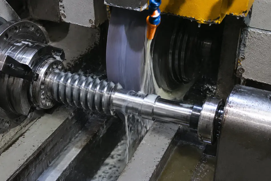
A high-performance butterfly valve's defining characteristic is its eccentric disc geometry — double-offset or triple-offset. This geometry is precisely what delivers tight shutoff and long seat life. It also produces a torque curve that behaves nothing like a gate valve or a resilient-seated butterfly valve.
The eccentricity means that the torque demand is not uniform across the travel arc. At the unseating moment — the instant the disc begins to lift off the seat — the required torque peaks sharply. Once the disc clears the seat, torque drops rapidly and remains relatively low through the mid-travel range.
This means gearbox selection based on average operating torque will fail at the most critical moment: initial opening.
Why a Single Safety Factor Is Not Enough
Standard gearbox selection practice applies one safety factor to the maximum torque figure. For an HPBV, this is insufficient. Engineers who understand eccentric valve behaviour apply separate safety factors at two points:
- Unseating torque — the peak demand at initial opening, which can be two to three times higher than mid-travel torque in some triple-offset designs
- Running torque — the sustained demand through mid-travel, which governs the gearbox's thermal and fatigue rating
Applying the same safety factor to both points leads to one of two outcomes:
- Under-ratio gearbox: Fast operation, but the actuator trips on overload at every opening cycle, or manual operation requires extreme effort at the handwheel
- Over-ratio gearbox: Reliable opening, but unnecessarily slow operation and increased cost
Gearbox Ratio Selection Logic for HPBV
A structured approach to ratio selection for eccentric butterfly valve applications:
- Obtain the valve's unseating torque at maximum differential pressure — this is the governing torque figure
- Apply a safety factor of 1.5× to 2.0× to the unseating torque for the gearbox output rating
- Confirm that the selected ratio still delivers acceptable operating speed for the application
- Verify the actuator input torque rating against the gearbox input requirement at unseating — not at running torque
This approach prevents the common failure where an actuator or handwheel is sized against average torque and then struggles or stalls at every opening stroke.
What Is the Difference Between Torque-Seated and Position-Seated Valve Sealing?
This distinction is the most important engineering concept in HPBV gearbox selection, and it is the one most frequently overlooked during procurement.
A standard resilient-seated butterfly valve seals by position. The disc reaches a defined angular position, the rubber seat elastomer deforms against it, and the seal is achieved. The gearbox's mechanical stop defines that position, and the sealing force is largely self-contained within the elastomer.
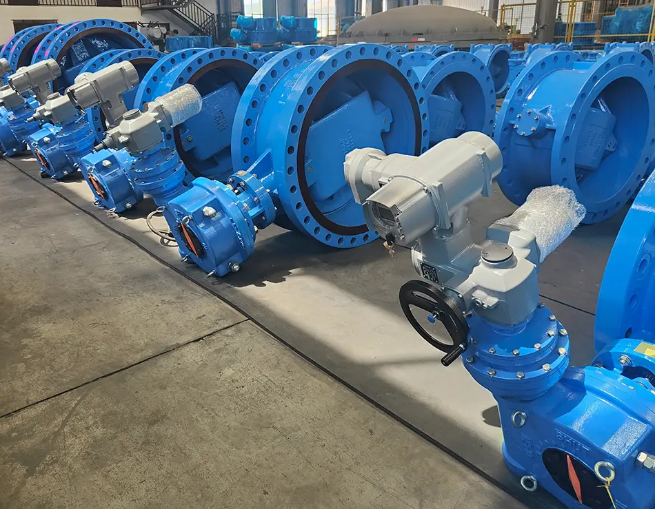
A triple-offset butterfly valve (TOBV) seals by torque2. The metal-to-metal seating geometry means the disc only achieves a reliable seal when the gearbox delivers a specific closing torque against the seat — and maintains it. Position alone is not enough.
The Mechanical Stop and Structural Rigidity Problem
This is where gearbox structural rigidity becomes more important than output torque magnitude. If the gearbox is:
- Too flexible — the housing deflects under high closing torque, absorbing torque in structural deformation rather than transmitting it to the seat
- Mechanically stop-set incorrectly — the disc stops before reaching the required seating position, leaving a gap in the metal-to-metal contact zone
...the valve will leak at pressure regardless of how many times the packing and seat are adjusted. I have encountered field complaints where a valve was blamed for poor sealing quality when the actual problem was a gearbox housing with insufficient wall section and incorrectly set mechanical stops.
Evaluating Gearbox Output Precision and Rigidity
For HPBV applications, buyers should evaluate:
- Mechanical stop adjustability: Confirm that stop screws are accessible, lockable, and set with documented angular precision — typically within ±0.5° for triple-offset applications
- Housing material section thickness: Ductile iron provides significantly better rigidity than grey iron at equivalent weight3; aluminium die-cast housings are generally unsuitable
- Output shaft bearing specification: Tapered roller or angular contact bearings resist combined radial and axial loading better than simple ball bearings
- Torsional stiffness documentation: Some gearbox suppliers can provide this on request — it is rarely on standard datasheets but is highly relevant for torque-seated applications
The key insight here: for a triple-offset butterfly valve, the precision and rigidity of the gearbox output are more critical selection criteria than peak torque capacity alone.
How Does Radial Bearing Load from the Valve Disc Affect Gearbox Life?
A butterfly disc sits suspended across the full bore of the pipeline. Under pressure, the differential force across the disc face is enormous — and because the disc is not centrally balanced against that force4 (particularly in offset designs), a significant radial load is transmitted up the valve stem and into whatever is connected at the top.
In a gear operator application, that means the radial load transmits directly into the gearbox's output shaft and bearings. This load is not captured in a standard torque calculation.
Why Compact Coupling Designs Create Long-Term Failures
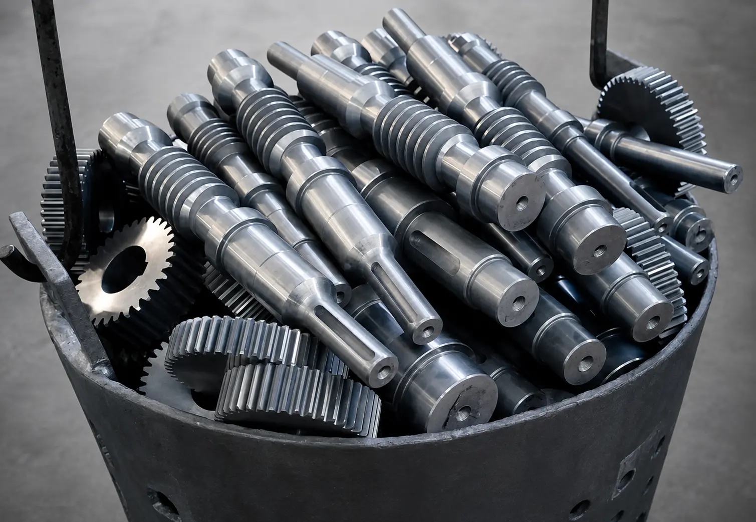
Many gearboxes designed for lighter-duty butterfly valve service use a compact, closely toleranced coupling between the gearbox output shaft and the valve stem. This coupling design minimises assembly height and simplifies installation.
Under radial loading from a high-pressure HPBV application, the same compact coupling provides no radial load relief. The full stem radial force is transferred to the gearbox output bearing — a bearing rated for torsional load, not combined radial and torsional loading.
The consequences appear gradually:
- Output bearing wear increases
- Gear mesh alignment shifts
- Oil seal lip loads increase
- Within 6–18 months: oil leakage, gear noise, or complete output shaft seizure
Mitigation Approaches for High-Pressure HPBV Applications
| Approach | Application |
|---|---|
| Flexible coupling with radial float | Allows limited radial displacement, reducing bearing load transfer |
| Heavy-duty output bearing specification | Angular contact or tapered roller bearings with higher radial rating |
| Enlarged bearing housing | Provides greater bearing contact area and load distribution |
| Intermediate support bracket | Carries radial stem load independently, isolating gearbox from stem forces |
For buyers procuring gearboxes for HPBV service above DN300 or above Class 150 pressure rating, I recommend raising the coupling and output bearing design specifically with your gearbox supplier before purchase order.
Are Low-Cost Gearboxes an Acceptable Risk on High-Performance Butterfly Valves?
The commercial pressure to reduce unit cost on gearbox selection is real. And for a standard lined butterfly valve in a low-pressure water service application, a light-duty cast aluminium or thin-shell grey iron gearbox may be entirely appropriate.
The problem arises when that same procurement logic is applied to a high-performance butterfly valve in a high-differential-pressure application. These are fundamentally different operating conditions, and the gearbox specification must reflect that difference.
The Material Specification Minimum for HPBV Service
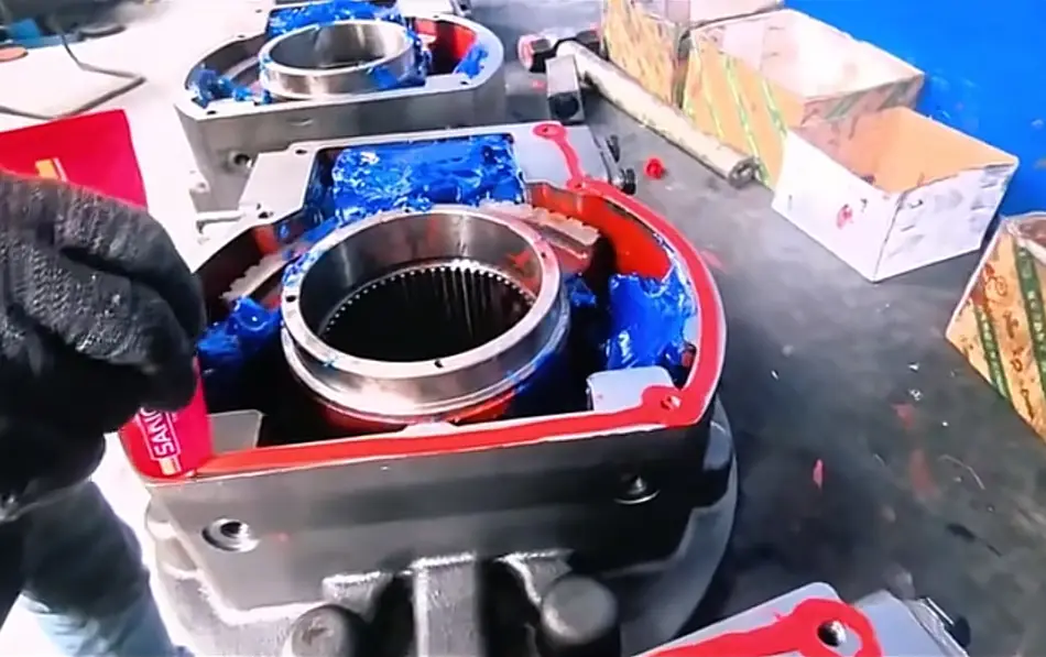
For high-performance butterfly valve applications — particularly triple-offset or double-offset designs operating at elevated pressure differentials — the minimum gearbox material specification should be:
Housing:
- Grey iron (GG25 / HT250) is the baseline, but ductile iron (GGG40 / QT400) is strongly preferred for applications above Class 150
- Aluminium die-cast housings should be avoided entirely in high-pressure HPBV service
Worm Wheel:
- Aluminium bronze (C95400 or equivalent) is the correct specification for HPBV service5
- Standard tin bronze or cast iron worm wheels are not suitable for the cyclic peak loads generated at HPBV unseating
Worm Shaft:
- Case-hardened alloy steel with ground thread profile6
- Surface hardness should be verified against the worm wheel material to ensure correct tribological pairing
Why This Matters at Unseating
At the moment of unseating on a high-pressure triple-offset valve, the gearbox experiences:
- Maximum output torque demand
- Maximum disc radial load on the stem
- Maximum input torque from the actuator or handwheel
If the housing material cannot contain these combined stress peaks without elastic deformation, the housing can crack along casting sections — an event that is sudden, dangerous, and difficult to predict from normal visual inspection7 of the installed gearbox.
A structured procurement approach should treat gearbox housing material as a technical requirement derived from valve operating conditions — not as a cost variable.
Frequently Asked Questions
What safety factor should I apply when sizing a gearbox for a triple-offset butterfly valve?
Apply separate safety factors for unseating torque and running torque. A factor of 1.5× to 2.0× applied to the maximum unseating torque at design differential pressure is a reasonable starting point. Running torque safety factors can be lower — typically 1.25× to 1.5×. Confirm the approach with your valve and gearbox supplier before finalising selection.
Can I use the same gearbox I use for lined butterfly valves on a high-performance butterfly valve?
Generally, no. Lined butterfly valves are position-seated and generate relatively uniform, low torque demands. High-performance butterfly valves — especially triple-offset designs — are torque-seated, generate sharp unseating torque peaks, and impose significant stem radial loads. The gearbox specification must be upgraded to match these conditions.
How do I know if a gearbox is genuinely self-locking for my application?
Request the gearbox manufacturer's confirmed self-locking ratio specification. Worm gearboxes with lead angles below approximately 5° are generally self-locking8, but the actual self-locking condition depends on the worm and worm wheel material combination, lubrication, and operating temperature. For critical HPBV applications, request written confirmation that the gearbox is self-locking under the expected output torque loading.
What documents should I request when qualifying a gearbox supplier for HPBV service?
Request: material certificates for housing, worm wheel, and worm shaft; dimensional inspection records confirming ISO 5211 interface compliance9; torque testing records; worm wheel gear processing inspection; and documentation of mechanical stop adjustment range and locking method. Verify that test conditions reflect HPBV operating demands, not light-duty defaults.
Does gearbox housing material affect sealing performance in a torque-seated valve?
Yes, indirectly. A housing with insufficient rigidity will deflect under high closing torque, absorbing seating force in structural strain rather than transmitting it to the valve seat. This reduces the effective seating torque at the disc-seat interface and can cause persistent leakage that is difficult to diagnose. Ductile iron housings with adequate wall section are the correct specification for torque-seated HPBV applications.
Conclusion
Pairing a gearbox with a high-performance butterfly valve requires a level of engineering evaluation that goes well beyond standard torque multiplication. The key takeaways are clear: fluid dynamic torque demands self-locking verification, eccentric geometry demands separate safety factors at unseating and running points, torque-seated designs demand gearbox rigidity and precise mechanical stops, disc radial loads demand appropriate bearing and coupling design, and high-pressure HPBV service demands heavy-duty material specifications — ductile iron housings and aluminium bronze worm wheels are not optional upgrades.
Every one of these failure modes is preventable with the right supplier conversation and the right technical documentation at the selection stage.
If you are procuring gearboxes for high-performance butterfly valve applications and want to review your selection criteria against these engineering requirements, contact TFC's engineering team for a technical evaluation of your application conditions.
"Transient Effects on Dynamic Torque for Butterfly Valves", https://digitalcommons.usu.edu/cgi/viewcontent.cgi?article=1253&context=gradreports. Studies of butterfly valve fluid dynamics have documented flow-induced torque acting on the disc as a function of opening angle and flow velocity, with the hydrodynamic component becoming dominant at large diameters and high velocities; see, e.g., research on disc torque coefficients in pipeline valve hydraulics. Evidence role: mechanism; source type: research. Supports: That fluid flow generates a hydrodynamic moment on a butterfly valve disc, particularly at partial opening and high flow velocities. Scope note: Quantitative values vary significantly with disc geometry, pipeline diameter, and flow regime; general fluid mechanics sources may not address HPBV-specific eccentric disc profiles ↩
"Butterfly Valves — Triple Offset Design • CGIS", https://cgis.ca/articles/butterfly-valves-triple-offset-design/. Valve engineering standards and manufacturer technical literature describe the triple-offset butterfly valve sealing mechanism as torque-dependent: the conical disc geometry creates a seal only when sufficient closing torque is applied to achieve full metal-to-metal contact across the seating surface. Evidence role: definition; source type: institution. Supports: That triple-offset butterfly valves rely on applied closing torque to achieve metal-to-metal sealing, distinguishing them from resilient-seated designs that seal by disc position. Scope note: Specific torque requirements for sealing are design- and pressure-class-dependent; this citation supports the general sealing principle rather than quantitative seating torque values ↩
"The Differences Between Ductile Iron and Gray Iron Castings", https://www.pentictonfoundry.com/news/differences-between-ductile-iron-and-gray-iron-castings-ductile-vs-gray-iron/. Materials engineering references document that ductile (nodular) iron, such as GGG40/QT400, exhibits significantly higher tensile strength, yield strength, and elongation than grey iron grades such as GG25/HT250, owing to the spheroidal graphite microstructure; elastic modulus values are comparable between the two grades. Evidence role: general_support; source type: research. Supports: That ductile iron has superior mechanical properties to grey iron, including higher tensile strength and impact resistance at comparable density. Scope note: Rigidity in a structural component depends on section geometry as well as material modulus; the claim that ductile iron provides better rigidity at equivalent weight is accurate for strength-limited designs but requires qualification for stiffness-limited applications ↩
"3.3 Design Basis Valve Stem Torque", https://www.nrc.gov/docs/ml1134/ml11347a386.pdf. Valve engineering references describe the net pressure force on a butterfly disc as the product of differential pressure and effective disc area; in offset designs, the geometric eccentricity means this force is not balanced about the stem axis, producing a bending moment and radial stem load that increases with pressure class and valve diameter. Evidence role: mechanism; source type: education. Supports: That differential pressure acting on a butterfly valve disc generates a net force on the disc that is transmitted as a radial load through the valve stem to connected components. Scope note: The magnitude of the radial stem load is highly dependent on the specific offset geometry and pressure rating; general references may not provide values applicable to a specific HPBV design ↩
"Aluminum Bronze Worm Gear Alloy", https://eureka.patsnap.com/materials/aluminum-bronze-worm-gear. Gear engineering literature and material standards identify aluminium bronze alloys as suitable worm wheel materials for high-load applications, citing their higher tensile strength and fatigue resistance compared to tin bronze, alongside acceptable tribological compatibility with hardened steel worm shafts. Evidence role: mechanism; source type: research. Supports: That aluminium bronze is a preferred worm wheel material for demanding cyclic load applications due to its strength, wear resistance, and fatigue properties. Scope note: Material performance is application-specific; the superiority of aluminium bronze over tin bronze depends on load magnitude, lubrication regime, and operating temperature, and is not universally applicable across all worm gear service conditions ↩
"Worm Gears | KHK Gear Manufacturer", https://khkgears.net/new/worm_gear.html. Gear engineering standards such as AGMA 6022 and ISO 14521 specify worm shaft material and surface treatment requirements, with case-hardened alloy steel and ground thread profiles identified as appropriate for high-load worm gear applications to achieve the hardness differential and surface finish necessary for acceptable wear rates with bronze worm wheels. Evidence role: expert_consensus; source type: institution. Supports: That worm shafts in industrial gearboxes are specified in case-hardened alloy steel with ground flanks to achieve the surface hardness and profile accuracy required for efficient power transmission and long service life. Scope note: Specific hardness and material grade requirements vary by standard edition and application class; the article's specification should be verified against the applicable standard for the pressure and duty class of the installation ↩
"Recommendations for Ductile and Brittle Failure Design ...", https://rampac.energy.gov/docs/default-source/nrcinfo/nureg_3760.pdf. Materials engineering literature characterises grey cast iron as a brittle material with low elongation at fracture and high notch sensitivity; under overload conditions, grey iron components can fail by sudden brittle fracture without significant prior plastic deformation or visible surface cracking, making failure prediction from visual inspection unreliable. Evidence role: mechanism; source type: research. Supports: That grey cast iron components can fail by brittle fracture under overload conditions with little prior visual indication, due to the material's low ductility and notch sensitivity. Scope note: This citation supports the general failure behaviour of grey cast iron; the specific claim that gearbox housing failures are unpredictable in HPBV service is contextual and would require field failure data for direct substantiation ↩
"Understanding Worm Gearbox Self-Locking and Back ...", https://industrialmonitordirect.com/blogs/knowledgebase/understanding-worm-gearbox-self-locking-and-back-drive-prevention?srsltid=AYCX9vJLACqOCs5eahN7BRjNAseA0nqZIgSsSebTyMcHigC-wOAqcP_5. Mechanical engineering references establish that a worm gear is self-locking when the lead angle is less than the friction angle between the worm and wheel materials; the commonly cited threshold of approximately 5° assumes typical lubricated steel-on-bronze contact conditions. Evidence role: definition; source type: education. Supports: That worm gear self-locking is determined by the relationship between lead angle and friction angle, with low lead angles preventing back-driving. Scope note: The precise threshold depends on the coefficient of friction, which varies with lubrication, surface finish, and operating temperature; the 5° figure is an approximation, not a universal standard ↩
"GEMCO ISO 5211 Standards.indd", https://www.strahmangroup.com/wp-content/uploads/2026/06/GEMCO-ISO-5211-Standards.pdf. ISO 5211 (Industrial valves — Part-turn actuator attachment) defines the dimensional requirements for the mounting flange, drive shaft, and fastener pattern connecting part-turn actuators and gear operators to industrial valves, providing a standardised interface that enables interchangeability between compliant components. Evidence role: definition; source type: institution. Supports: That ISO 5211 is the international standard specifying the mounting interface dimensions between industrial valves and their actuators or gear operators. Scope note: ISO 5211 covers dimensional interface requirements only; compliance with ISO 5211 does not address torque capacity, material specification, or suitability for a specific valve duty ↩