MOTORIZED MULTI-TURN VALVE AUTOMATION ENGINEERING
Electric-ready Bevel Gear Operators
Engineered for Reliable Motorized Multi-turn Valve Automation
TFC Electric-ready Bevel Gear Operators form the mechanical transmission platform between the selected electric actuator and the multi-turn valve. The system aligns the actuator input flange, coupling, bevel gear transmission, output sleeve, stem nut and valve mounting interface so motor torque can be converted into controlled continuous valve movement.
CATEGORY PRODUCT RANGE
Explore Electric-ready Bevel Gear Operator Products
Compare motor-ready bevel gear platforms by output torque, gear ratio, actuator input interface, output sleeve, stem interface, thrust configuration and valve application. Final selection must verify the complete actuator–gearbox–valve transmission path.
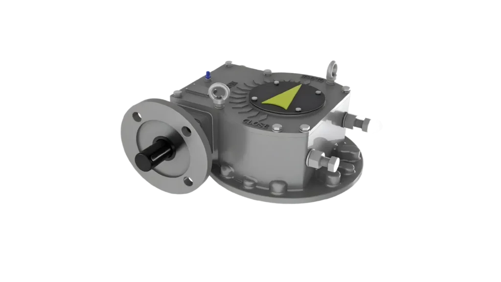 GL Platform
- Output
- Continuous Multi-turn
- Valve Application
- Electric-ready quarter-turn valve gearbox
ENGINEERING DEFINITION
What Is an Electric-ready Bevel Gear Operator?
It is not an electric actuator and it does not independently provide remote control, feedback, diagnostics or DCS / SCADA communication. Those functions are provided through the selected electric actuator and plant control system.
The gearbox provides the controlled mechanical transmission path between the actuator and gate valves, globe valves, knife gate valves, penstocks, sluice gates and other continuous multi-turn mechanisms.
WHY ELECTRIC-READY MATTERS
Prepare Today’s Valve for Reliable Automation
Electric-ready engineering reduces interface uncertainty when a valve is motorized at initial installation or upgraded later.
Direct Actuator Integration
Purpose-defined motor flange and coupling geometry reduce field modification.
Protected Valve Investment
A prepared transmission platform can simplify future automation upgrades.
Controlled Alignment
Actuator, input drive, gear set and output axis are reviewed as one transmission chain.
Balanced Actuator Loading
Gear ratio and efficiency are selected to keep actuator torque and speed within an appropriate operating range.
OEM Repeatability
Approved interfaces can become controlled configurations for repeat valve production.
SIGNATURE ENGINEERING MODULE
Motor-ready Design Explained
A dependable automated valve package is created by engineering every mechanical interface as one complete transmission system.
ELECTRIC ACTUATOR INTEGRATION WORKFLOW
From Motor Output to Controlled Valve Movement
The gearbox does not add automation intelligence. It preserves the mechanical relationship required for the actuator to move the valve accurately and reliably.
Mechanical Transmission
The gearbox redirects actuator rotation through 90 degrees and delivers continuous multi-turn output.
Remote Control Authority
Remote operation, indication, feedback and diagnostics come from the selected actuator and control system.
Positioning Accuracy
Backlash, coupling fit, shaft alignment and actuator control strategy influence final positioning performance.
Lifecycle Access
Mounting, lubrication, inspection access and replaceable interface parts should be considered during integration.
MOTOR-READY INTERFACE ENGINEERING
Four Interfaces Must Be Defined Separately
A single reference to an “ISO interface” is not enough. The actuator input, gearbox mounting, output sleeve and valve structure perform different functions.
Actuator Input Flange
Connects the electric actuator housing to the gearbox input side.
- ISO, MSS or DIN patterns where applicable
- Project-specific drilling patterns
- Flange size and torque capacity verification
Input Coupling
Transfers actuator output-shaft torque into the gearbox input drive.
- Shaft form and dimensions
- Key, spline or drive profile
- Engagement length and alignment
Gearbox Mounting Base
Connects the gearbox structure to the valve yoke, bracket or thrust base.
- Bolt pattern and locating geometry
- Structural load path
- Access and service orientation
Output Sleeve & Stem Nut
Transfers rotational output to the valve stem while respecting the valve’s thrust arrangement.
- Bore, thread or key geometry
- Replaceable stem-nut options
- Thrust-taking or non-thrust configuration
ELECTRIC ACTUATOR COMPATIBILITY
Electric Actuator Compatibility
Compatibility depends on verified torque, speed, duty, flange, coupling and environmental requirements—not on actuator type alone.
MANUAL VS MOTORIZED OPERATION
Choose the Operating Architecture Around the Plant Requirement
Manual and Electric-ready bevel gear operators share the same fundamental multi-turn transmission principle but serve different operating strategies.
Manual Bevel Gear Operator
- Handwheel input
- Local operator control
- Manual positioning
- No independent remote feedback
- Best for accessible, lower-frequency operation
Motor-ready Bevel Gear Operator
- Electric actuator input
- Local or remote operation through the actuator
- On-off or modulating control where specified
- DCS / SCADA communication through the actuator and plant system
- Prepared for automated multi-turn valve packages
ENGINEERING FEATURES
Built for Reliable Automated Multi-turn Valve Systems
Each configuration is reviewed around actuator performance, transmission efficiency, valve torque, thrust, interface geometry and environmental duty.
Actuator Integration
Purpose-defined motor mounting, coupling and input-drive geometry.
- ISO / MSS / DIN where applicable
- Project-specific flange patterns
- Actuator brand integration
Transmission System
Precision bevel gear geometry for efficient continuous right-angle transmission.
- Alloy steel gear options
- Controlled backlash
- Heavy-duty bearing arrangements
Thrust Configuration
Load path selected according to the valve yoke, stem nut and bearing architecture.
- Thrust-taking configurations
- Non-thrust configurations
- Optional separate thrust arrangements
Housing & Protection
Enclosed industrial construction for outdoor and process environments.
- Ductile iron housing options
- Weather-resistant sealing
- Long-life lubrication
Modular Interfaces
Configurable input and output components support multiple valve platforms.
- Output sleeves
- Replaceable stem nuts
- Custom yoke mounting
OEM Engineering
Controlled configurations for repeat integration into customer valve ranges.
- Approved interface drawings
- Customer branding and coatings
- Traceable configuration records
ENGINEERING SELECTION GUIDE
Select the Complete Automation Transmission System
The gearbox cannot be selected correctly from valve size or actuator flange alone.
Define the Valve
Confirm valve type, size, stem movement and mounting structure.
Verify Torque & Thrust
Use verified break, running and seating torque together with axial load.
Define Duty & Speed
Review starts per hour, modulating duty and required operating time.
Select the Actuator
Confirm actuator output torque, speed, control mode and environmental certification.
Optimize Gear Ratio
Balance actuator loading, valve operating speed and transmission efficiency.
Verify Every Interface
Confirm input flange, coupling, mounting base, output sleeve and stem nut.
TYPICAL VALVE APPLICATIONS
Designed for Automated Continuous Multi-turn Valves
Application selection follows valve operating principle, torque, thrust and automation requirements.
Gate Valves
Motorized isolation of rising-stem resilient-seated and metal-seated gate valves.
Globe Valves
Automated isolation or regulating service where the selected actuator and gearbox support the required positioning duty.
Knife Gate Valves
Remote operation for slurry, wastewater, mining and process isolation duties.
Penstocks & Sluice Gates
Motorized water-level and flow-control mechanisms for dams, hydropower, irrigation and treatment plants.
Rising-stem Control Gates
Motorized multi-turn operation for engineered gate mechanisms using verified stem, stem-nut and thrust arrangements.
Custom Multi-turn Mechanisms
Project-specific motorized right-angle drives for special gates, stems and industrial mechanisms.
INDUSTRIAL AUTOMATION ENVIRONMENTS
Supporting Critical Infrastructure and Process Systems
OEM AUTOMATION INTEGRATION
Build a Repeatable Motorized Valve Platform
TFC works with valve manufacturers, actuator suppliers, EPC contractors and system integrators to convert approved interface data into controlled gearbox configurations.
Electric Actuator Integration
Input flange, coupling, ratio, torque and speed matching.
- Actuator make and model review
- Mounting drawing confirmation
- Manual override coordination where applicable
Valve Interface Engineering
Mounting base, output sleeve, stem nut and thrust arrangement.
- Valve yoke verification
- Stem geometry control
- Thrust load-path confirmation
Custom Manufacturing
Customer-specific interfaces, coatings, identity and documentation.
- OEM nameplates and logo
- Project coatings
- Controlled repeat configurations
Automation Package Support
Engineering data for gearbox-only or complete actuator–gearbox packages.
- General arrangement drawings
- Interface drawings
- Inspection and traceability records
ENGINEERING DOCUMENTATION
Resources for Selection, Approval and Integration
Documentation is prepared according to the approved gearbox, actuator, valve and project configuration.
Technical Datasheets
Torque, ratio, dimensions, duty, interfaces and operating characteristics.
General Arrangement Drawings
Actuator, gearbox, valve and mounting geometry.
Interface Drawings
Input flange, coupling, output sleeve, stem nut and valve mounting details.
Inspection & Traceability
Material, dimensional, functional and project-identification records where specified.
KNOWLEDGE CENTER
Motorized Multi-turn Valve Automation Knowledge Cluster
Expand your understanding of actuator integration, multi-turn transmission and interface engineering.
RELATED PRODUCT PLATFORMS
Complete Your Valve Operating System
ENGINEERING FAQ
Electric-ready Bevel Gear Operator Engineering FAQ
MOTORIZED MULTI-TURN VALVE AUTOMATION ENGINEERING
Configure the Mechanical Platform Behind Reliable Valve Automation
Submit the valve, torque, thrust, actuator, duty, speed and interface information. TFC will review the complete actuator–gearbox–valve transmission path before recommending a configuration.