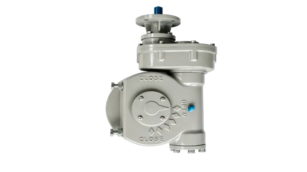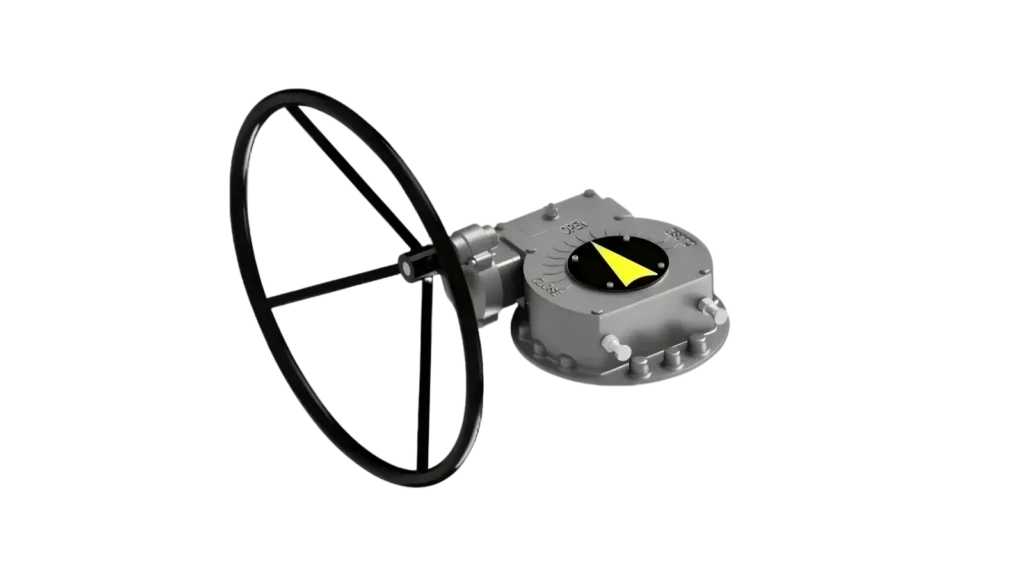
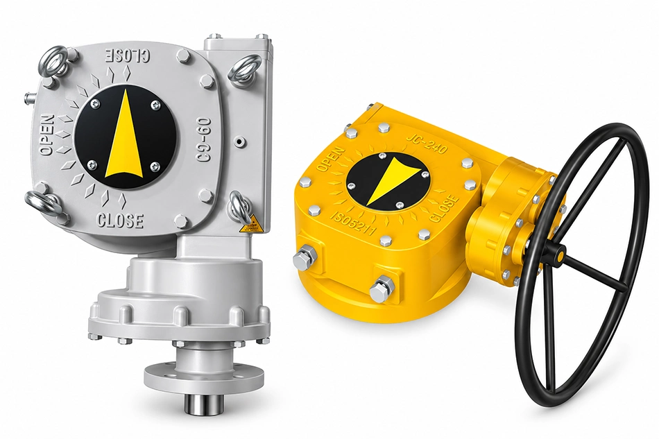
Torque matching for a critical ball valve sounds like a straightforward lookup — until you sit across from a valve engineer who has already ordered the gearbox and is now wondering why it struggles at line pressure. That gap between catalog torque and real operating torque is where selection errors live, and in critical service applications, those errors surface at the worst possible moments.
Pairing the perfect gearbox with a critical ball valve requires more than matching torque figures from a datasheet. The real selection sequence must account for differential pressure at closing, stem friction coefficients, cycle frequency, fluid type, temperature, and ISO 5211 interface compatibility. Skipping any of these variables does not simplify the process — it shifts the risk from the specification stage to the installation stage.

The technical depth behind this decision is exactly what most online guides avoid. They offer size charts and move on. What follows is a structured walkthrough of the variables that actually determine whether a gearbox will perform reliably in service — the kind of analysis that separates a considered engineering decision from an educated guess.
Why Does the "Right Size" Gearbox Still Fail on a Critical Ball Valve?
Engineers who have specified gearboxes for years can still encounter this problem. A gearbox that looks correctly rated on paper produces sluggish operation or fails to achieve full torque output when installed on an operating line.
The core issue is that catalog torque ratings are reference values, not operating guarantees. Most valve torque figures are published at zero differential pressure, with clean media, at ambient temperature.1 Real process conditions introduce compounding friction, pressure-driven seal loading, and stem resistance that can push actual breakaway torque significantly above the catalog number.

Understanding why this happens requires pulling apart the actual torque demand at the valve stem — not just reading the specification sheet.
The Catalog Torque Trap
In my experience consulting on ball valve gearbox selections, the most common opening statement from customers is: "The valve is rated at X Nm, so we need a gearbox that handles X Nm." That framing is technically incomplete, and it leads to undersized selections more often than oversized ones.
Here is why it matters:
- Catalog torque is typically measured at zero differential pressure (DP). The valve manufacturer tests the bare valve under no-load fluid conditions.
- In service, differential pressure at the moment of closing or opening creates an additional force on the ball. This force increases stem friction and seal compression resistance.
- Seal material and condition amplify the effect. New PTFE seats behave differently from aged or temperature-cycled seals. Fire-safe seats add further resistance.2
- The stem friction factor (often called the stem factor or Cf) converts differential pressure force into torque demand.3 This coefficient varies by valve design, seat material, and stem geometry — and it is rarely published in the same document as the base torque figure.
The practical result: two physically identical 8-inch ball valves from different manufacturers can have meaningfully different actual operating torques under the same line conditions, even if their catalog torque ratings are identical.
What "Critical Service" Changes About the Calculation
The word "critical" in critical ball valve is not decorative. It changes the engineering logic in two ways:
- Failure consequence is higher. A valve that fails to close in a process shutdown scenario may not just cause maintenance downtime — it can compromise safety systems, contaminate product streams, or trigger environmental incidents.4
- The operating envelope is wider. Critical valves tend to operate across temperature ranges, pressure cycles, and media variations that normal service assumptions do not cover. Selecting to the nominal condition understates the real demand.
This is why torque matching for critical valves is a risk-reduction exercise, not a parameter lookup. The goal is not to find the smallest gearbox that technically clears the catalog torque. The goal is to find the gearbox that will reliably deliver the required torque across the full operating envelope, including the worst-case scenario the process team hopes never happens.
What Variables Actually Drive Gearbox Torque Demand in Ball Valve Applications?
Most selection guides list operating torque as a single input. In practice, it is the output of several interacting variables. Understanding these individually is what allows an engineer to build a defensible safety margin rather than guess at one.
The primary variables driving actual gearbox torque demand are: differential pressure at valve close or open position, stem friction factor, seal type and condition, fluid viscosity and contamination level, operating temperature, and valve size and bore geometry. No single variable can be assessed in isolation — they interact, and they compound.
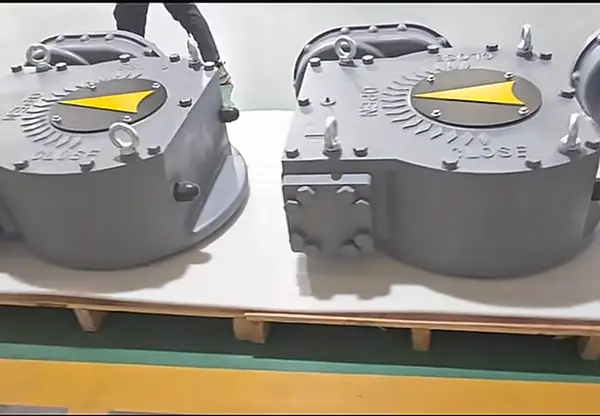
Differential Pressure: The Most Commonly Skipped Input
In my experience, differential pressure is the variable most frequently omitted from initial gearbox inquiries. A customer will specify valve size, mounting standard, and desired output torque — and then, when asked about differential pressure at close, the response is often a pause followed by "we'll need to check."
For a ball valve operating in pipeline service, the differential pressure at the moment of breaking away from the closed position is one of the most significant torque contributors5. The relationship is direct: higher DP increases the lateral force on the ball, increases seat contact pressure, and increases the torque required to initiate rotation.
The practical implication is that a gearbox correctly rated for a valve operating at low DP may be inadequate for the same valve operating at higher line pressure — even though the valve itself is unchanged.
Stem Factor and Seal Resistance
The stem factor (Cf) quantifies how efficiently the valve converts stem torque into rotational force at the ball. It is influenced by:
- Stem diameter and geometry
- Bearing type and condition
- Seal material (PTFE, reinforced PTFE, elastomeric, fire-safe)
- Packing gland load
A well-maintained valve with fresh PTFE seats will have a lower effective friction factor than the same valve after extended service cycling, or after a thermal excursion that has caused packing consolidation6. Gearbox selection based on new-valve assumptions may be inadequate for the valve at mid-life.
Fluid Type and Contamination
| Fluid Condition | Effect on Torque Demand | Relative Risk Level |
|---|---|---|
| Clean gas, low pressure | Minimal seat loading, low viscosity drag | Low |
| Clean liquid (water, light hydrocarbons) | Moderate seat loading at pressure | Moderate |
| Viscous fluids (heavy oil, slurry) | High resistance at ball surface, elevated breakaway | High |
| Slurry / particulate media | Solid infiltration into seat and stem — torque spikes unpredictably | Very High |
| High-temperature steam or process fluid | Seal expansion, packing consolidation, potential thermal binding | High to Very High |
Clean gas at moderate pressure is a very different selection problem from slurry service at the same nominal pressure. Treating them identically is a specification error.
How Does Cycle Frequency Affect Gearbox Safety Factor Selection?
A ball valve that operates once per day in steady-state pipeline service presents a fundamentally different fatigue and wear profile than one cycling every 15 minutes in a batch process. Yet both are sometimes evaluated against the same catalog torque figure with the same assumed safety margin.
Cycle frequency determines how quickly a gearbox accumulates mechanical fatigue, gear wear, and lubricant degradation.7 High-frequency cycling in demanding media conditions typically requires a higher applied safety factor and a more conservative gearbox rating than low-cycle critical isolation service. Typical safety coefficient ranges vary by application type — engineering confirmation is required before applying any specific figure to a critical application.
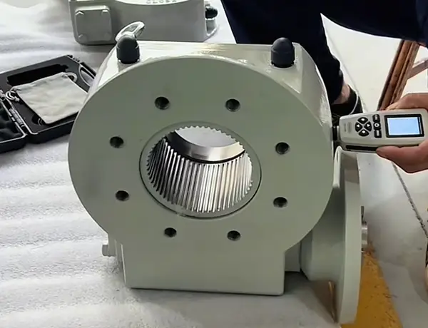
Mapping Application Type to Safety Factor Logic
The specific safety factor for any given application must be confirmed by the valve and gearbox engineers together, taking into account all operating variables. However, in broad terms, typical engineering practice maps application types into tiers:
-
Low-frequency critical isolation service (e.g., once daily, clean gas or liquid, stable temperature): Safety factor applied to the calculated operating torque is typically in a lower range. The main concern is adequate torque margin for emergency operation, not component fatigue.
-
Moderate-frequency process control service (e.g., multiple cycles per shift, standard liquids, moderate temperature variation): Safety margin increases to account for wear-induced torque growth over time. The gearbox must perform reliably as seals and bearings age.
-
High-frequency or severe service (e.g., cycling every few minutes, slurry media, elevated temperature, contamination risk): Engineering practice typically applies a substantially higher safety coefficient. The priority shifts from torque margin to durability, and gearbox component ratings — not just output torque — become critical selection criteria.
The insight here is that the safety factor is not a fixed multiplier you apply to the catalog torque and move on. It is a judgment that reflects operating severity, maintenance access, consequence of failure, and expected service life. In my experience, the most productive conversations with valve engineers happen when we work through these factors explicitly, rather than anchoring on a single multiplier.
What Changes in Gearbox Specification Under High Cycle Loads
Under high-frequency operation, the selection criteria expand beyond torque rating:
- Gear material and hardness — softer materials wear faster under repeated loading
- Lubrication type and service interval — grease-packed gearboxes may require relubrication at intervals that are impractical in high-cycle service8
- Housing seal integrity — repeated thermal cycling and contamination exposure demand robust sealing to protect internal components
- Bearing load rating — radial loads from differential pressure translate into bearing wear over high cycle counts
Addressing these factors requires moving beyond the torque column of a product datasheet.
Why Is ISO 5211 Interface Compatibility a Late-Stage Failure Point?
This is the part of the selection process that experienced engineers wish someone had told them earlier. The torque is confirmed. The gearbox model is selected. The order is placed. And then the mounting dimensions or stem bore create an installation problem that was entirely avoidable.
ISO 5211 defines the standard flange and drive connection dimensions for mounting gearboxes and actuators to valve stems.9 However, compliance with ISO 5211 does not guarantee interchangeability — flange size, bore diameter, keyway configuration, and stem length must all be confirmed against the specific valve before finalizing a gearbox selection.
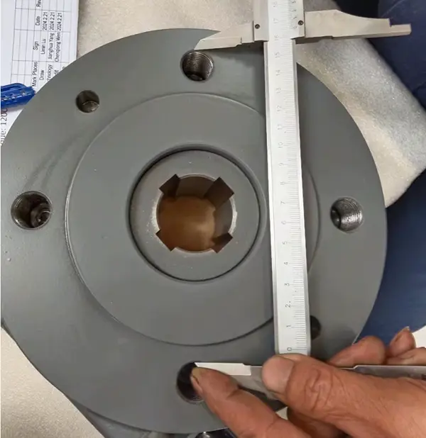
Why "ISO 5211 Compliant" Is Not Enough
ISO 5211 establishes a range of flange sizes (F03 through F48 and beyond) and corresponding bore and keyway dimensions.10 A gearbox carrying an F10 flange designation is compatible with other F10 components in theory — but in practice, several additional dimensions must match:
- Stem bore diameter. The gearbox input bore must accommodate the valve stem without excessive clearance or interference. Tolerances matter in precision applications.
- Keyway dimensions. Standard key sizes are specified, but valve manufacturers sometimes use non-standard or proprietary key configurations on critical service valves.
- Stem height (S-dimension). The distance between the valve mounting flange face and the end of the stem varies by manufacturer. A gearbox with insufficient input depth will not engage the stem fully.
- Mounting bolt circle and bolt size. These are defined by the flange standard, but bolt pattern confirmation is still part of responsible procurement.
The consequence of discovering a mismatch after delivery is a project delay at minimum and, in some EPC scenarios, a significant contractual problem.
Where This Should Sit in the Selection Sequence
In my experience, the most efficient approach is to treat interface confirmation as a parallel step to torque calculation, not a subsequent one. The selection sequence that avoids late-stage problems looks like this:
- Define operating conditions (DP, fluid, temperature, cycle frequency)
- Calculate required operating torque with appropriate safety margin
- Confirm ISO 5211 flange size, bore, keyway, and stem dimensions simultaneously
- Verify gearbox output shaft matches valve stem geometry
- Confirm actuator interface if electric actuation is planned
- Request engineering drawings from the gearbox supplier for dimensional verification
- Final review before purchase order
Step 3 sitting in parallel with step 2 — rather than after it — is the sequence change that eliminates the late-stage discovery problem.
Frequently Asked Questions
How do I find the actual operating torque for a ball valve under line pressure?
The starting point is the valve manufacturer's torque specification, which typically states conditions (DP, media, temperature). If operating conditions differ from those stated, request the valve manufacturer's torque calculation procedure or safety factor guidance. For critical applications, confirm actual operating torque with the valve manufacturer directly rather than extrapolating from catalog figures.
Is a higher safety factor always better for gearbox selection?
Not unconditionally. An oversized gearbox introduces its own concerns: higher operating loads on the valve stem, additional weight on the valve topworks, potential actuator sizing mismatches, and unnecessary cost.11 The goal is an appropriate safety factor matched to the specific operating severity — not the largest possible margin.
What does ISO 5211 actually standardize, and what does it leave open?
ISO 5211 standardizes the mounting flange dimensions, bolt circle, bore and keyway dimensions, and torque ratings for each flange size. It does not standardize stem height, extended bonnet configurations, or proprietary drive arrangements. Confirmation of all interface dimensions against the specific valve design remains a buyer responsibility.
Can the same gearbox model be used across different valve sizes?
Potentially, where operating torques overlap and interface dimensions are compatible. However, this requires individual confirmation for each valve size and application. Gearbox torque ranges cover spans, but operating conditions — not valve size alone — determine whether a given model is appropriate.
When should we involve the gearbox supplier in the selection process?
As early as possible, and certainly before finalizing valve assembly drawings or project specifications. A gearbox supplier with ball valve application experience should be able to request the relevant operating condition data and flag interface risks before the order stage. Late involvement increases the probability of discovery problems.
Conclusion
Gearbox selection for a critical ball valve is not resolved by matching a catalog torque number to a product datasheet. The real engineering work is in identifying the variables — differential pressure, stem factor, fluid type, cycle frequency, temperature — that determine what the valve actually demands under service conditions. Applying an appropriate safety margin requires understanding the application severity, not applying a standard multiplier.
Interface compatibility, particularly ISO 5211 stem bore and dimensional confirmation, belongs in the selection sequence alongside torque calculation — not after it. These two tracks executed in parallel prevent the late-stage discovery problems that cost projects time and budget.
If your team is evaluating gearbox suppliers for a critical ball valve application, the quality of the technical conversation at the inquiry stage is itself a selection signal. A supplier who asks about differential pressure, cycle frequency, and interface dimensions before quoting is demonstrating the kind of application awareness that matters when the gearbox needs to perform reliably under real process conditions.
We work with valve manufacturers and OEM partners through exactly this selection process. If you have a specific application where the operating conditions make the torque matching genuinely complex, we welcome that kind of engineering conversation.
"How to Calculate Ball Valve Torque for Actuator Sizing | IMD", https://industrialmonitordirect.com/blogs/knowledgebase/ball-valve-torque-calculation-for-actuator-sizing?srsltid=AYCX9vKQwZ7dvpedpg2xz2OGwqnKvGEFFLZdiLrJdLuQz6D5ZynmVxRk. Industry valve standards such as API 6D and ISO 17292 specify the test conditions under which valve torque is measured and reported; these conditions typically involve zero or minimal differential pressure and clean test media, which may differ substantially from process operating conditions. Evidence role: general_support; source type: institution. Supports: That published valve torque ratings are measured under defined reference conditions, typically zero or low differential pressure, which differ from actual service conditions.. Scope note: These standards define test methodology but do not themselves quantify the magnitude of torque increase under real operating conditions, which varies by valve design. ↩
"Valve Seats and Seals Selection Guide for Industrial Valves", https://valveman.com/blogs/the-valve-authority/valve-seats-and-seal-selection-guide?srsltid=AYCX9vI0K5fpYMdIMhyKOoJjtK8NimtiHvgYimjGp7ADb3YX9FpVcjJc. Studies on PTFE tribological properties document increased friction coefficients following thermal cycling and creep deformation, while fire-safe seat designs typically employ spring-loaded metallic backup seats that impose higher contact forces than standard soft seats, both effects contributing to elevated operating torque. Evidence role: mechanism; source type: research. Supports: That PTFE seat material properties change with thermal cycling and aging, and that fire-safe seat designs impose higher contact forces, both of which increase valve operating torque.. Scope note: Quantitative torque increases are highly design-specific and cannot be generalized without reference to a particular valve manufacturer's test data. ↩
"Motor Operated Valves Course - 03 - Design Basis ...", https://www.nrc.gov/docs/ML1134/ML11347A380.pdf. The stem factor (Cf) is an empirically derived coefficient used in valve torque calculations to relate differential pressure-induced forces on the closure element to the torque required at the stem; its value depends on valve geometry, seat material, and bearing configuration. Evidence role: definition; source type: institution. Supports: The definition and role of the stem friction factor in converting differential pressure and seat forces into required operating torque for rotary valves.. Scope note: The stem factor is not universally standardized across valve manufacturers, and published values may reflect idealized rather than in-service conditions. ↩
"Hazard and Operability Study (HAZOP) – SAFEChE", https://safeche.engin.umich.edu/tutorials/hazop-tutorial/. Process safety frameworks, including IEC 61511 (Functional Safety: Safety Instrumented Systems for the Process Industry) and OSHA Process Safety Management regulations, identify valve failure as a credible initiating or enabling event for process safety incidents, including loss of containment, safety system impairment, and environmental releases. Evidence role: general_support; source type: institution. Supports: That failure of isolation valves in critical service can have safety, environmental, and operational consequences beyond simple maintenance downtime.. Scope note: These frameworks address safety instrumented systems broadly; the specific consequence severity for any given valve failure depends on process conditions, redundancy, and facility-specific risk assessments. ↩
"3.3 Design Basis Valve Stem Torque", https://www.nrc.gov/docs/ml1134/ml11347a386.pdf. Engineering analyses of rotary valve torque components identify differential pressure-induced lateral loading on the ball as a primary driver of breakaway torque, with the contribution scaling with both pressure magnitude and ball diameter. Evidence role: mechanism; source type: research. Supports: That differential pressure acting on the ball at the closed position generates lateral forces that significantly increase the torque required to initiate rotation.. Scope note: The relative contribution of differential pressure versus other torque components varies by valve design and seat configuration, so general references may not apply directly to all valve types. ↩
"What are Bolt Torque Considerations for Valve Packing ...", https://www.pumpsandsystems.com/article/what-are-bolt-torque-considerations-valve-packing-ensure-reliable-performance/. Materials science literature on PTFE creep behavior documents that PTFE packing undergoes cold flow and consolidation under sustained compressive load and thermal cycling, reducing packing volume and potentially increasing contact pressure on the stem, with consequent increases in stem friction torque. Evidence role: mechanism; source type: research. Supports: That valve stem packing materials, particularly PTFE-based packings, undergo creep and consolidation under thermal cycling, which can increase gland load and stem friction torque.. Scope note: The magnitude of torque increase from packing consolidation depends on packing design, gland geometry, and thermal history, and may not be predictable from general PTFE creep data alone. ↩
"A New High-Speed, High-Cycle, Gear-Tooth Bending ...", https://ntrs.nasa.gov/api/citations/20110012902/downloads/20110012902.pdf. Gear fatigue theory, as described in standards such as ISO 6336 and AGMA 2101, establishes that fatigue damage accumulates as a function of load cycle count, with higher cycle frequencies accelerating both surface fatigue and lubricant degradation through increased thermal loading. Evidence role: mechanism; source type: research. Supports: That the number of load cycles is a primary determinant of fatigue life and wear accumulation in gear systems, and that lubricant degradation rate is related to operating frequency and thermal cycling.. Scope note: These references address gear fatigue in general mechanical applications; specific behavior in valve gearbox service depends on load profile, duty cycle, and environmental conditions. ↩
"Lubrication Explained: Types, Functions, and Examples", https://precisionlubrication.com/articles/lubrication/. Lubrication engineering references document that grease service life in enclosed gear systems is a function of operating temperature, load, and cycle frequency, with high-frequency cycling accelerating oxidative degradation and mechanical shear of the grease structure, potentially requiring relubrication intervals shorter than those specified for standard-duty applications. Evidence role: general_support; source type: research. Supports: That grease lubrication life in mechanical systems is finite and dependent on operating frequency, temperature, and load, and that high-cycle applications may exhaust grease service life faster than maintenance schedules allow.. Scope note: Specific relubrication intervals depend on grease formulation, operating conditions, and gearbox design; general references provide guidance but not application-specific intervals. ↩
"ISO Mounting Dimensions", https://www.valvesonline.com.au/references/iso-mounting-dimensions/?srsltid=AYCX9vIUbP3O7y08nTsV6yg10sDsnFpYqNKYXzl4lj4MVe5o_E7MbkTB. ISO 5211:2017 (Industrial valves — Part-turn actuator attachment) specifies the dimensions of flange connections, including bolt circles, bore diameters, keyway configurations, and torque ratings, for mounting part-turn actuators to valves. Evidence role: definition; source type: institution. Supports: That ISO 5211 specifies the mounting flange dimensions, bore, keyway, and torque ratings for connecting actuators and gearboxes to industrial valves.. Scope note: The standard defines interface geometry but explicitly does not cover all dimensional variables such as stem height or extended bonnet configurations, which must be confirmed separately. ↩
"ISO Mounting Dimensions", https://www.valvesonline.com.au/references/iso-mounting-dimensions/?srsltid=AYCX9vLr9-WTY50SZwJqGwcgy45FQqEgmzig8xPNfsYowBJlB6eLjPFo. ISO 5211:2017 tabulates flange size designations from F03 through F48, with each size specifying nominal bore diameter, keyway width and depth, bolt circle diameter, and maximum torque rating, providing the dimensional basis for actuator-to-valve interface compatibility assessment. Evidence role: general_support; source type: institution. Supports: That ISO 5211 specifies a series of flange size designations with defined bore diameters, keyway dimensions, bolt circles, and torque ratings for each size.. Scope note: The standard is subject to revision; users should confirm the current edition and any national or industry-specific amendments applicable to their jurisdiction or project specification. ↩
"Common Valve Actuator Sizing Mistakes to Avoid", https://arpcovalves.com/blog/common-valve-actuator-sizing-mistakes-to-avoid/. Valve engineering guidance documents, including those published by the Valve Manufacturers Association (VMA) and actuator suppliers, note that actuator torque output should be matched to valve stem torque capacity to avoid stem yielding or structural damage, indicating that oversizing carries mechanical risk as well as cost implications. Evidence role: general_support; source type: institution. Supports: That applying excessive torque to a valve stem through an oversized actuator or gearbox can impose structural loads beyond the stem's design capacity.. Scope note: Specific stem load limits are valve-design-dependent; general guidance establishes the principle but quantitative limits require reference to the valve manufacturer's engineering data. ↩